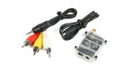
Tarot 5.8Ghz FPV Receiver


Tarot 5.8Ghz FPV Receiver
Copy and Share the Below URL


The Tarot 5.8Ghz FPV receiver is specifically designed for long distance AV reception.
It offers 4 bands and 32 x 5.8Ghz channels and has excellent channel lock for added security. This simple and easy to use receiver system is compact & super lightweight and is the perfect solution for all FPV pilots, especially those on a limited budget.
An ideal companion for FPV LCD monitor screens.
Features:
• 32 channels Covering A, B, E and F bands with auto lock
• 7.4 to 12.6v power input range
• Dual A/V outputs
• 5- DIP switch
• Light weight
Specs:
Dimensions: 28 x 46 x 40mm
Weight: 10.5g
Operating Frequency: 5645-5945MHZ
Channel: 4 Band/32 Channels
Receiving Sensitivity: -85dbm
Input Voltage: DC 7-26V (2~6S)
Antenna Adaptor:RP-SMA50ohms
Operating Temperature: -10 ~ 60 degrees
Frequency:FM/PLL
AV output: 2.5mm 4pin AV output
Power Input: 3.5mm(Exterior) 1.3mm (interior)DC
Includes:
Receiver
3.5mm power cable
2.5mm AV cable
User Guide
Requires:
RP-SMA receiver antenna (see accessory listing below)
NOTE: Always install your antenna before connecting power to the receiver to avoid damage to the unit and do not overload the input voltage.
Samuel | Verified Buyer
-
Overall
-
Quality
-
Value
Receiver working with video on red cable
Oct 31, 2017
Ryan | Verified Buyer
-
Overall
-
Quality
-
Value
Receiver Working, Cable Miswired
Jan 04, 2017
Ryan | Verified Buyer
-
Overall
-
Quality
-
Value
Miswired Lead, but a working reciever
Jan 04, 2017
CMANERO | Verified Buyer
-
Overall
-
Quality
-
Value
Certified Buyer Rated
Feb 17, 2016
Travis | Verified Buyer
-
Overall
-
Quality
-
Value
Customer Rated
Jan 28, 2016
| Video output unvalid oscillogram | Download [154] |
Only registered users can upload files.
Please log in or register to start helping your fellow hobbyists today!