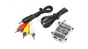
サプライヤーになる ブログ 新しいアイテム
新規登録

合計金額

¥0.00

ショッピングカート 0 ショッピングカート 0 Loading...

タロット5.8GHz帯FPVレシーバー

Generating Links

タロット5.8GHz帯FPVレシーバー

価格:

Now save 節約 ¥0.00 ¥0.00

¥3,362.17
購入済み Discontinued Product

Please continue searching for a similar product.
SKU:
297000306-0
送料無料したい? クリックする こちらへ 詳細情報を参照する

タロット5.8GHz帯FPV受信機は、特に長距離のAV受信用に設計されています。

これは、4バンドと32×5.8GHz帯のチャンネルを提供し、セキュリティを強化するための優れたチャネルロックしています。この単純な受信機システムを使用して簡単には、コンパクト&超軽量であり、特に、すべてのFPVパイロット、限られた予算上の方に最適なソリューションです。

FPV液晶モニター画面のための理想的なコンパニオン。

特徴:
オートロック付きA、B、E、Fのバンドをカバー•32チャンネル
•7.4〜12.6Vの電源入力範囲
•デュアルA / V出力
•5 DIPスイッチ
•軽量

仕様:
寸法:28のx 46のx 40ミリメートル
重量:10.5グラム
動作周波数:5645-5945MHZ
チャンネル:4バンド/ 32チャンネル
受信感度:-85dbm
入力電圧:7-26V DC(2〜6S)
アンテナアダプター:SMA50ohms
動作温度:-10〜60度
周波数:FM / PLL
AV出力:2.5ミリメートル4ピンのAV出力
電源入力:3.5ミリメートル(エクステリア)1.3ミリメートル(内装)DC

含まれています:
受信機
3.5ミリメートル電源ケーブル
2.5ミリメートルのAVケーブル
ユーザーガイド

必要なもの:
SMAの受信アンテナ(以下付属品リストを参照してください)

:必ず、ユニットへの損傷を避けるために、受信機に電源を接続する前に、あなたのアンテナを設置し、入力電圧が過負荷にならないでください。

動画をアップロードする

動画をアップロードするには登録してください サインイン または 新規登録

トピック
並び替え
最新のトピック
* ニックネーム:

* あなたの返信:


下のフィールドに画像に表示されているテキストを入力してください
*検証コード:
キャンセル
提出する
新しいトピックを投稿する
* ニックネーム:

* あなたのトピック:


下のフィールドに画像に表示されているテキストを入力してください
*検証コード:
投稿トピック

レビューを書くために登録してください サインイン または 新規登録

Samuel | 確認済みの購入者

  • Overall
  • Quality
  • Value

Receiver working with video on red cable

Oct 31, 2017

I have the same problem as Ryan, video is not on the yellow but on the red... And audio doesn't work with the Quanum FPVme... I have paid for something good, not wrong !!!

Ryan | 確認済みの購入者

  • Overall
  • Quality
  • Value

Receiver Working, Cable Miswired

Jan 04, 2017

Out of the box i could not get the thing working, however being an electrical engineer i decided to pull the thing down and figure out what went wrong, (tldr - it works just flip yellow and white)

First off its based on the RTC6715 receiver IC, meaning its made exactly like a 5808 module with a power supply and a video / audio lead already bolted on, the 5 way bank of switches just go to a em78p153 micro that then controls the thing by SPI so its easy to hack into, and the RF module seems to be well made,

There is an RSSI pin on the side of the module when you open the case, seems to be 0.8-2.2V, (if you plan to use it for diversity)

Now back to the wiring fault, on my one its actually the white plug that has the video, if yours doesnt work on that plug, then internally if you have the AV plug pointing down and look on the side with the metal can, video is the 6th pin from the left, and the plug makes reliable contact fully seated.

For people who want the rest, starting from the left, my camera lacks audio so i could not test it.
Pin 1 is 3.3V,
Pin 2 is switch 4
Pin 3 is ground
Pin 4 is presumed audio (to yellow plug)
Pin 5 is presumed audio (to red Plug)
Pin 6 is video (to white plug)
Pin 7 is switch 1
Pin 8 is switch 2
Pin 9 is switch 3
Pin 10 is switch 5

the soldering was fine on both modules, and it is working well now that i understand the miswiring.

Ryan | 確認済みの購入者

  • Overall
  • Quality
  • Value

Miswired Lead, but a working reciever

Jan 04, 2017

Out of the box i could not get the thing working, however being an electrical engineer i decided to pull the thing down and figure out what went wrong, (tldr - it works just flip yellow and white)

First off its based on the RTC6715 receiver IC, meaning its made exactly like a 5808 module with a power supply and a video / audio lead already bolted on, the 5 way bank of switches just go to a em78p153 micro that then controls the thing by SPI so its easy to hack into, and the RF module seems to be well made,

There is an RSSI pin on the side of the module when you open the case, seems to be 0.8-2.2V, (if you plan to use it for diversity)

Now back to the wiring fault, on my one its actually the white plug that has the video, if yours doesnt work on that plug, then internally if you have the AV plug pointing down and look on the side with the metal can, video is the 6th pin from the left, and the plug makes reliable contact fully seated.

For people who want the rest, starting from the left, my camera lacks audio so i could not test it.
Pin 1 is 3.3V,
Pin 2 is switch 4
Pin 3 is ground
Pin 4 is presumed audio (to yellow plug)
Pin 5 is presumed audio (to red Plug)
Pin 6 is video (to white plug)
Pin 7 is switch 1
Pin 8 is switch 2
Pin 9 is switch 3
Pin 10 is switch 5

the soldering was fine on both modules, and it is working well now that i understand the miswiring.

CMANERO | 確認済みの購入者

  • Overall
  • Quality
  • Value

Certified Buyer Rated

Feb 17, 2016

Buen producto y barato. lo uso en un NighHawks 280

Travis | 確認済みの購入者

  • Overall
  • Quality
  • Value

Customer Rated

Jan 28, 2016

Dud... Screwed on an antenna, adjusted frequencies accordingly, applied power, and could NOT get the thing to output any signal what so ever... I'm either doing something wrong or I got a dud. Either way, it's cheaply priced so not a huge loss.

顧客ファイル
Video output unvalid oscillogram Download [154]
ファイルをアップロードする

ファイルをアップロードするには登録してください.
お願いします サインイン または 新規登録 今すぐ愛好家を助け始めましょう!