Building turnouts or points for a model railway is actually very common and easy to do. There are many reasons that you might want to build a set of points. Not only is it considerably cheaper to build your own but there is tremendous satisfaction when the points are completed and your rolling stock runs through smoothly.
Of course, building your own points allows you to make a set of points to suit the layout perfectly as opposed to fit your track to the points your hobby shop had in stock. You don't have to wait until the store opens or the snow clears. Provided you have a few basic components you can fabricate a set of points in between half an hour to an hour. The more you make the better you'll get at it. It might take you a few attempts to get it right to start out simple first and work your way up to more complicated trackwork.
So once you've made a few points you inevitably decide to build a large set of points (because you can) and you'll then need to electrify it. A single set of points is not too difficult however a double crossover is a little tricky. Depending on the direction of travel different parts of the rail change polarity and so we can use Arduino with a few low-cost components and a little logic. Not only can we use Arduino to move the railhead through a servo but also change the polarity of the track. If you like we could also set signal lights and just about anything else but more on that later.
What is Arduino?

Arduino is an open-source electronics platform based on easy to use hardware and software. Arduino boards are able to read inputs - light on a sensor, a finger on a button, or even a Twitter message and then turn it into an output - activating a motor, turning on an LED, publishing something online. You can tell your board what to do by sending a set of instructions to the microcontroller on the board. To do so you use the Arduino programming language (based onWiring), and the Arduino Software (IDE), based on Processing. To read more about Ardunio, go here.
What else can Arduino do on a model railroad?
The list is endless, from lights to signals, to the DCC controller. Arduino is a low cost, yet powerful system that is relatively easy to learn once you get started. In this article, I'll show you how to control several servos that can be used to throw points easily. Servos are cheap, reliable, quiet, and easy to configure. So after deciding to build several turnouts for my new layout I also built a double crossover and I wanted to throw the points easily, at the flick of a switch you might say. I had some 9-gram low-cost servos laying around that were us perfect for the job.
What is a Servo?
A Servo is a small device that incorporates a micro motor, a gear train, a potentiometer, an integrated circuit, and an output shaft. Of the three wires that stick out from the motor casing, Two are for power (positive and ground) and the other is a control input line. It is this signal wire that we connect to the Arduino board and can send a position signal.
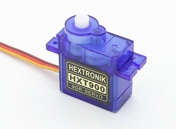
Servos are readily available in a variety of sizes. My preference from past experience in RC aircraft is the well-known HXT900, which is available to buy from HobbyKing. Super reliable and they even stock spare gears for this model. Servos are used in a wide variety of applications ranging from the RC hobby industry, industrial, medical, and even military. The servo is essentially controlled by a signal of variable width known as PWM (Pulse Width Modulation). The pulse is sent via the signal wire on the servo with the other two wires for positive/ negative current.
What hardware is required?
- 1 x Arduino Board Uno Board
- 1 x Push Button Switch
- 1 x Kingduino Compatible Sensor Shield V2.0
- 1 x Relay board
- 1 x Soldering iron and rosin flux solder
- 1 x Bag of servo extension leads and lengths of wire
What Software is required?
Installing Arduino.
- Install the Arduino software, follow the prompts, etc
- Open Arduino, and from the menu bar select tools, boards, and select Arduino/Genuino Uno.
- Copy and paste the code below into Arduino and upload it to the board. To upload press the Forward arrow located at the top, far left, next to the check tick
Connecting the hardware
- You will need to solder wires onto each of the 4 segments of the crossover.
- Start by following the picture below a wire the relay board the same.
The wires do not need to be soldered as they can be screwed into place.
- You can now connect the Arduino board and the sensor board together.
- Power the board up and copy the code below to Arduino and write it to the board.
- If using the expansion board, insert header pins into the ground (GND) and VCC (5v+).
- Connect header pins 1-8 on the relay board to the Arduino board as per the Arduino sketch. You can of course choose any pins you like by editing the sketch.
Relay1 = 22; Relay2 = 23; Relay3 = 24; Relay4 = 25; Relay5 = 26; Relay6 = 27; Relay7 = 28; Relay8 = 29; Relay9 Relay10
- Connect your momentary switched to the ground and signal wire of pins 1 and 3.
- Connect your servos to ground, positive and signal positions on the board. 2,3,40. You may be wondering why one point uses an additional servo signal position. As it turns out, there is no standard direction of travel with servo manufacturers. So when I installed the first set of servos I needed to reverse the direction of one servo. Hence why I tacked on another servo on pin40. When I installed the second set of servos they operated in opposite directions so I only needed a y-lead and no further code to actuate.
- At this point, you can power it all up and start testing. Exciting right!
- If you're using the prototype expansion board take a look at all of those empty pins. They can run LED's, record input from reed switches, RFID chips, sound modules, and just about anything you could chuck at it.
The Arduino Code
Copy and paste everything in between the stars into Arduino IDE and write to the board ************************************************************************************************* #include //We use this to turn on an LED on the arduino board each time the button is pressed. Its great for trouble shooting. const int ledPin = 13; // We are using the arduino Mega256 and the Mega Sensor Shield and i've opted to use pins 1-2 for once side of the double cross over and pins 3-4 for the other side. // I have used pins 22-29 for the relay pins however you could use other pins if you desired. // You can repeat the code and use up to pins 53 which gives us about 25 servos that we can control. // Don't use pin 13 because that is used by the led. We use the LED in the code to determine if the switch is functioning) // I've included 2 examples and you are free to use these as you please. It is as simple as adding more lines to this code. const int buttonPin1 = 1; //active low const int servoPin1 = 2; const int servoPin40 = 40; const int Relay1 = 22; const int Relay2 = 23; const int Relay3 = 24; const int Relay4 = 25; const int buttonPin2 = 3; //active low const int servoPin2 = 4; const int Relay5 = 26; const int Relay6 = 27; const int Relay7 = 28; const int Relay8 = 29; //single switch with uses a double pole double throw relay to control polarity of the frog. const int buttonPin3 = 5; //active low const int servoPin3 = 6; const int Relay9 = 30; const int buttonPin4 = 7; //active low const int servoPin4 = 8; const int Relay10 = 31; // We use a flag count to count the number of times we have cycled the servo with a buttom press. We only what the servos to cycle one // This is because I've written the sketch so that the servo pushes had against the rail then moves the arm slightly back. // This is because a servo will buzz if pressure is applied constantly and it would become quite annoying. int buttonState1 = 0; int flag1=0; int buttonState2 = 0; int flag2=0; int buttonState3 = 0; int flag3=0; int buttonState4 = 0; int flag4=0; // This is where we define servos Servo servo1; Servo servo2; Servo servo3; Servo servo4; Servo servo40; void setup() { //Input or output? pinMode(ledPin, OUTPUT); pinMode(buttonPin1, INPUT_PULLUP); pinMode(buttonPin2, INPUT_PULLUP); pinMode(buttonPin3, INPUT_PULLUP); pinMode(buttonPin4, INPUT_PULLUP); servo1.attach(servoPin1); servo2.attach(servoPin2); servo3.attach(servoPin3); servo4.attach(servoPin4); servo40.attach(servoPin40); pinMode(Relay1, OUTPUT); pinMode(Relay2, OUTPUT); pinMode(Relay3, OUTPUT); pinMode(Relay4, OUTPUT); pinMode(Relay5, OUTPUT); pinMode(Relay6, OUTPUT); pinMode(Relay7, OUTPUT); pinMode(Relay8, OUTPUT); pinMode(Relay9, OUTPUT); pinMode(Relay10, OUTPUT); // When the servos first turn on they are prone to make a noise. This over time can cause the servos to fail and in addition its bloddy noisy. // This simply moves them hard against the rail head then comes back just enough so that the servo does not buzz. servo1.write(84); servo1.write(78); servo1.write(80); servo40.write(79); servo40.write(88); servo40.write(87); servo2.write(84); servo2.write(79); servo2.write(80); servo3.write(84); servo3.write(79); servo3.write(80); servo4.write(84); servo4.write(79); servo4.write(80); digitalWrite(Relay1, HIGH); //write 0 or low to led pin digitalWrite(Relay2, HIGH); //write 0 or low to led pin digitalWrite(Relay3, HIGH); //write 0 or low to led pin digitalWrite(Relay4, HIGH); //write 0 or low to led pin digitalWrite(Relay5, HIGH); //write 0 or low to led pin digitalWrite(Relay6, HIGH); //write 0 or low to led pin digitalWrite(Relay7, HIGH); //write 0 or low to led pin digitalWrite(Relay8, HIGH); //write 0 or low to led pin digitalWrite(Relay9, HIGH); //write 0 or low to led pin digitalWrite(Relay10, HIGH); //write 0 or low to led pin flag1=1; flag2=1; flag3=1; flag4=1; } void loop(){ //Pins 1-2 Button1 Bottom Left Point of the cross over buttonState1 = digitalRead(buttonPin1); if (buttonState1 == LOW) { if ( flag1 == 0){ digitalWrite(ledPin, LOW); digitalWrite(Relay3, HIGH); //write 1 or HIGH to led pin digitalWrite(Relay6, HIGH); //write 0 or low to led pin digitalWrite(Relay5, HIGH); //write 1 or HIGH to led pin digitalWrite(Relay4, HIGH); //write 0 or low to led pin digitalWrite(Relay2, HIGH); //write 1 or HIGH to led pin digitalWrite(Relay8, HIGH); //write 0 or low to led pin digitalWrite(Relay1, HIGH); //write 1 or HIGH to led pin digitalWrite(Relay7, HIGH); //write 0 or low to led pin servo3.write(79); delay(100); servo3.write(80); flag3=0; digitalWrite(ledPin, LOW); digitalWrite(Relay3, LOW); //write 0 or low to led pin digitalWrite(Relay6, LOW); //write 0 or low to led pin digitalWrite(Relay5, LOW); //write 0 or low to led pin digitalWrite(Relay4, LOW); //write 0 or low to led pin digitalWrite(Relay1, LOW); //write 0 or low to led pin digitalWrite(Relay7, LOW); //write 0 or low to led pin servo1.write(88); servo40.write(74); delay(100); servo1.write(87); servo40.write(76); flag1=1; //change flag variable } else if ( flag1 == 1){ digitalWrite(ledPin, HIGH); digitalWrite(Relay3, HIGH); //write 1 or HIGH to led pin digitalWrite(Relay6, HIGH); //write 1 or HIGH to led pin digitalWrite(Relay5, HIGH); //write 1 or HIGH to led pin digitalWrite(Relay4, HIGH); //write 1 or HIGH to led pin digitalWrite(Relay2, HIGH); //write 1 or HIGH to led pin digitalWrite(Relay8, HIGH); //write 0 or low to led pin digitalWrite(Relay1, HIGH); //write 1 or HIGH to led pin digitalWrite(Relay7, HIGH); //write 0 or low to led pin servo1.write(78); servo40.write(88); delay(100); servo1.write(80); servo40.write(87); flag1=0; } } // Button 2 Pins 3-4 Bottom Right Point of the cross over buttonState2 = digitalRead(buttonPin2); if (buttonState2 == LOW) { if ( flag2 == 0){ digitalWrite(ledPin, HIGH); digitalWrite(Relay3, HIGH); //write 1 or HIGH to led pin digitalWrite(Relay6, HIGH); //write 1 or HIGH to led pin digitalWrite(Relay5, HIGH); //write 1 or HIGH to led pin digitalWrite(Relay4, HIGH); //write 1 or HIGH to led pin digitalWrite(Relay2, HIGH); //write 1 or HIGH to led pin digitalWrite(Relay8, HIGH); //write 0 or low to led pin digitalWrite(Relay1, HIGH); //write 1 or HIGH to led pin digitalWrite(Relay7, HIGH); //write 0 or low to led pin servo1.write(78); servo40.write(88); delay(100); servo1.write(80); servo40.write(87); flag1=0; digitalWrite(ledPin, LOW); digitalWrite(Relay3, LOW); //write 0 or low to led pin digitalWrite(Relay6, LOW); //write 0 or low to led pin digitalWrite(Relay5, LOW); //write 0 or low to led pin digitalWrite(Relay4, LOW); //write 0 or low to led pin digitalWrite(Relay2, LOW); //write 0 or low to led pin digitalWrite(Relay8, LOW); //write 0 or low to led pin servo2.write(88); delay(100); servo3.write(87); flag2=1; //change flag variable } else if ( flag2 == 1){ digitalWrite(ledPin, HIGH); digitalWrite(Relay3, HIGH); //write 1 or HIGH to led pin digitalWrite(Relay6, HIGH); //write 1 or HIGH to led pin digitalWrite(Relay5, HIGH); //write 1 or HIGH to led pin digitalWrite(Relay4, HIGH); //write 1 or HIGH to led pin digitalWrite(Relay2, HIGH); //write 1 or HIGH to led pin digitalWrite(Relay8, HIGH); //write 1 or HIGH to led pin servo2.write(79); delay(100); servo2.write(80); flag2=0; } } // Button 3 Pins 5-6 buttonState3 = digitalRead(buttonPin3); if (buttonState3 == LOW) { if ( flag3 == 0){ digitalWrite(ledPin, LOW); digitalWrite(Relay9, LOW); //write 1 or HIGH to led pin servo3.write(88); delay(100); servo3.write(87); flag3=1; //change flag variable } else if ( flag3 == 1){ digitalWrite(ledPin, HIGH); digitalWrite(Relay9, HIGH); //write 1 or HIGH to led pin servo3.write(79); delay(100); servo3.write(80); flag3=0; } } // Button 4 Pins 7-8 This option uses only a servo and no relay is driven. See the previos code for a relay. buttonState4 = digitalRead(buttonPin4); if (buttonState4 == LOW) { if ( flag4 == 0){ digitalWrite(ledPin, LOW); servo4.write(88); delay(100); servo4.write(87); flag4=1; //change flag variable } else if ( flag4 == 1){ digitalWrite(ledPin, HIGH); servo4.write(79); delay(100); servo4.write(80); flag4=0; } } //Small delay. This is to stop arduino picking up incorrect button states. delay(500); } ************************************************************************************ It is entirely possible to expand on this with more servos, switches and or course relay boards. As you have probably guessed there is a lot of space on the Arduino board so there is no need to stop here. Keep expanding and experimenting and there is nothing wrong with using another board to develop your code and when ready dump it across to your live production board.
- 54 digital input / output terminals
- 16 analog inputs
For some other useful accessories check out Kingduino MEGA ProtoShield V3 Expansion Board. Stay tuned for more projects using Arduino!