Tarot 5.8Ghz FPV-Empfänger

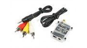


Tarot 5.8Ghz FPV-Empfänger


Der Empfänger Tarot 5.8Ghz FPV ist speziell für den Fern AV-Empfang ausgelegt.
Es verfügt über 4 Bands und 32 x 5,8 GHz-Kanäle und hat eine ausgezeichnete Kanalsperre für zusätzliche Sicherheit. Diese einfache und leicht Empfängersystem zu verwenden, ist kompakt und super leicht und ist die perfekte Lösung für alle FPV Piloten, vor allem solche mit einem begrenzten Budget.
Ein idealer Begleiter für FPV LCD-Bildschirme.
Eigenschaften:
• 32 Kanäle Abdeckung A, B, E und F Bänder mit Auto-Lock
• 7,4 bis 12,6 V Stromeingangsbereich
• Dual-A / V-Ausgänge
• 5- DIP-Schalter
• Geringes Gewicht
Specs:
Maße: 28 x 46 x 40mm
Gewicht: 10,5 g
Betriebsfrequenz: 5645-5945MHZ
Kanal: 4 - Band / 32 Kanäle
Empfangsempfindlichkeit: -85dBm
Eingangsspannung: DC 7-26V (2 ~ 6S)
Antennenadapter: SMA50ohms
Betriebstemperatur: -10 ~ 60 Grad
Frequenz: FM / PLL
AV - Ausgang: 2,5 mm 4 - Pin - AV - Ausgang
Leistungsaufnahme: 3,5 mm (Außen) 1,3 mm (innen) DC
Eingeschlossen sind:
Empfänger
3,5-mm-Stromkabel
2.5mm AV-Kabel
Benutzerhandbuch
Benötigt:
SMA Empfangsantenne (siehe Zubehör Liste unten)
HINWEIS: Immer Ihre Antenne installieren , bevor Sie den Receiver anschließen Schäden am Gerät zu vermeiden und nicht überlasten die Eingangsspannung.
Registrieren Sie sich bitte, um Videos hochzuladen anmelden oder Registrieren
Registrieren Sie sich bitte, um Bewertungen zu schreiben anmelden oder registrieren
Samuel | Verifizierter Käufer
-
Overall
-
Quality
-
Value
Receiver working with video on red cable
Oct 31, 2017
Ryan | Verifizierter Käufer
-
Overall
-
Quality
-
Value
Receiver Working, Cable Miswired
Jan 04, 2017
Ryan | Verifizierter Käufer
-
Overall
-
Quality
-
Value
Miswired Lead, but a working reciever
Jan 04, 2017
CMANERO | Verifizierter Käufer
-
Overall
-
Quality
-
Value
Certified Buyer Rated
Feb 17, 2016
Travis | Verifizierter Käufer
-
Overall
-
Quality
-
Value
Customer Rated
Jan 28, 2016
| Video output unvalid oscillogram | Download [154] |
Registrieren Sie sich, um Dateien hochzuladen.
Bitte anmelden oder registrieren um jetzt Hobbyisten zu helfen!