Introduction:
In the previous articles, we’ve covered what iNav is and what it can do for a fixed-wing pilot.
Adding iNavflight to your fixed-wing model can provide you will excellent stabilization and cheap, effective OSD setup but it can also provide GPS flight modes and allow you to even fly missions autonomously. Using a $20 flight controller and a $20 GPS unit we can create a ‘smart’ model that will rival some of the systems costing 10 times as much. In this article, we will continue to look at the technology and cover a little more about getting the software and starting to view up the flight controller between your radio and servos on your model. For this example, we will be using a fixed-wing but the same process can be applied to any type of ‘plane supported by iNav.
A word on choosing the flight controller and GPS...
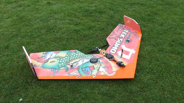
For this example, we will be using an Omnibus F3 AIO flight controller and an M8N GPS Module. The details for the supported boards and recommended hardware are changing all the time and updated in the Wiki (https://github.com/iNavFlight/inav/wiki). Before ordering a flight controller, take a look and see what the latest detail is. Ideally, for a fixed-wing plane, you will need at least 5 PWM outputs on the flight controller you use (throttle (2), elevator, rudder, and aileron). On a wing, you can use a flight controller with only four PWM outputs (throttle (2), elevon-R, and elevon-L). If you are looking to also use flaps and other controls then you may need a flight controller with more than these basic PWM outputs. For a fixed-wing model, iNav doesn’t need a compass or barometer on the flight controller. All of the direction information is calculated from the direction of travel and the height reported from the GPS unit. This makes setup and wiring very quick and easy for fixed-wing models, lucky for us eh? So, with that out of the way, let’s look at how you get iNav onto your computer and then look at the wiring for adding a flight controller to your model...
Downloading and installing iNavflight
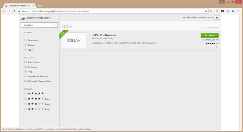
iNav runs as an application in Chrome so you’ll need to be running the Chrome Browser to run it at the moment. In Chrome, Google for ‘Chrome web store’ and then in the store search for iNavflight. The screen should look like the image above, click on the ‘Install’ icon on the right-hand side (ours says ‘Rate It’ as we’ve already installed it), and then it should install onto your computer.
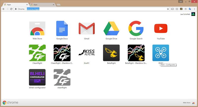
To see all of the installed apps in Chrome you can click on the icon for the apps on your desktop (looks like a white box with 9 colored boxes inside) or type ‘chrome://apps’ into the address bar. Now you’ve got the software on your computer then we can test the flight controller...
Testing your flight controller before you start...
I always recommend testing the flight controller before you start soldering anything and connecting any cables. There are a couple of reasons for this. The first is that if you find the board is defective at this early stage then you can contact the vendor and arrange for a replacement. Some vendors will not replace a flight controller that a builder has soldered. The second reason is that if the flight controller works in the test, and then stops working later then you can investigate the problem knowing that it could well be something you did that stopped the board working. All modern flight controllers come with the Micro-USD port at the side, simply plug the USB cable into the flight controller and wait for any drivers to install. Once complete, open iNav and then you should see that there is a COM port in the top right hand of the application. Click on the ‘connect’ button in the top right-hand corner and then move the flight controller and see that the image of the model on the screen moves too. If it does then we are looking good! It’s handy at this point to select the model type you will be using. The reason for this is that the numbers by the sides of the control surfaces/motors correspond to the PWM outputs on the flight controller, so by taking a note of this diagram in the top right of the screen we can make it easier for us as we start the wiring.
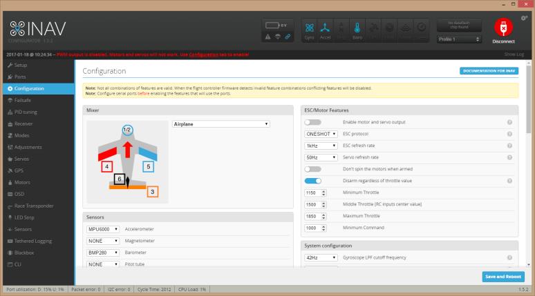
In this image, you can see that the motor will plus into PWM output 1, the left aileron into PWM output 4, the rudder into PWM output 6, and so on. Now we’ve got this connection diagram, we can start to wire up the pieces on the model...
Connecting the GPS to the flight controller
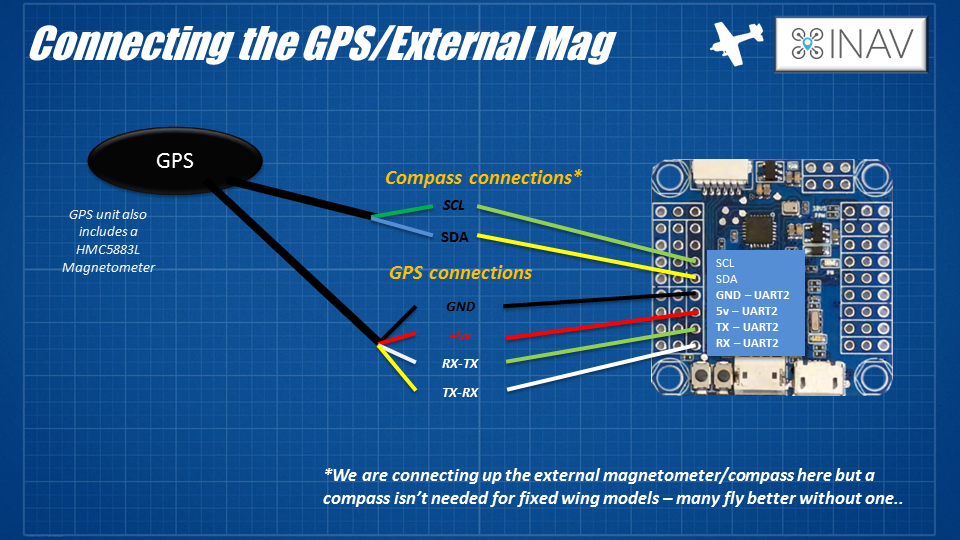
One of the main connections you’ll need to make is to connect the GPS unit (we’re using an M8N GPS here) to the flight controller. On the flight controller, you want to find a spare hardware UART port, UART 2 is normally the best bet. Out of the GPS unit, you’ll see six wires, four in one connector, and two in another. The four wires are for the GPS unit itself, they are the two power wires and two signal wires. You will need to connect then to the pins on UART2 on your flight controller. Black will be the GND wire, Red will be the +5v wire and the other two (usually something like Green, White or Yellow) will be the two receiver (Rx) and (Tx) wires. Don’t worry if you get the data connections the wrong way round, it will not damage anything. That isn’t the same for the power connections. Make sure that you have connected the power wires the right way as that may cause a problem if you manage to connect them the wrong way round. The other two wires coming from the GPS unit are for the external compass. These connect to the i2c pins on the flight controller but are not needed for a fixed-wing model. Again, these are data connections only so connecting them backward won’t hurt anything; it will just mean that the external compass will not work. For me, I’d leave it unconnected. When the flight controller powers up it will auto-configure the GPS unit and set it up to be how it needs to be for iNav. This is a great feature and saves us builders a lot of time!
Connecting the radio receiver
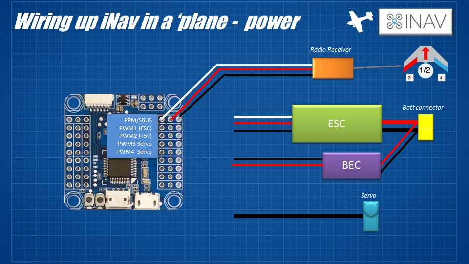
Now that the GPS is wired up, we need to start fitting the flight controller and GPS into the model. Unplug all of the servo connections from the receiver in the model (if it’s one you’ve already built and flown) and check to see if the receiver has a PPM or S-Bus output. In a traditional controller fixed-wing, the receiver simply sends the PWM values to the servos and ESC to match the position of the PWM signals it’s receiving from your radio. With a flight controller, the radio receiver sends the stick positions to the flight controller, and then the flight controller, running iNav, then decides the values to send to the servos and ESC. Flight controllers can have a few ways for you to connect your receiver to them using, here are a few of the most common... PWM – this is the method that most closely matches the connection method that fixed-wing pilots are most familiar with. One servo cable for each of the signals – one for throttle, another for Aileron, etc. Some of the latest flight controllers don’t support this kind of connection as it takes one pin for each channel and space is precious on modern, compact flight controllers. PPM – This is a single servo wire connection between the radio receiver and the flight controller. Each of the signals for the channels is sent one after the other. It makes the connection very simple to wire but the connection isn’t the fastest (but on a plane, it works very well). The other benefit is that it’s a very easy signal for the flight controller and iNav to understand so setup is easy. S-Bus – this is another single wire connection. Again, the channel values for each of the channels are sent one after the other but this time the signal is digital, like a computer cable. This is a very fast, reliable connection but does need some extra settings in iNav to make it work and you will have to dedicate a UART to help iNav ‘read’ the signals as they are inverted too (most F3 boards expect UART 3 to be dedicated to this job). There are other options to connect your receiver to the flight controller as well as these main three. You can use things like a Spektrum satellite receiver connected to the flight controller directly, handy when there isn’t much space. You can also use newer connections like I-Bus from vendors like FlySky. Have a look at the receiver you want to use and look for either a PPM or S-Bus connection first as they are the most widely supported and some of the easiest to setup. Once you’ve identified the pins on the receiver then you’ll need to wire them up to the corresponding pins on the flight controller. On ours here, the PPM and S-Bus connections would be wired to the same pins on the flight controller. On some others, there may be a different connector for PPM or S-Bus. Follow the instructions for your board.
Connecting the ESC and Motor(s)

The next thing to do is connect the power. Care needs to be taken here as the flight controller and GPS will take a little more current/power than a model without them. In a normal plane, you only have to worry about supplying the power for the servos and radio receiver. Here we also have a flight controller and GPS unit that will need clean 5v power too. The good news is that the extra current needed for these pieces isn’t a lot (well under an amp) but we do have to be careful about the 5v power dropping too low. Remember those horror stories from back in the day about radio receivers rebooting/hanging when the 5v voltage dipped? It’s a lot more exciting when it’s not just the radio receiver that can ‘lose its place’ when the power has problems. I’d recommend installing a good quality switched BEC rated well above the amperage you’ve been using in the model to date. If you’re using a 2A BEC, installed a switched 3A BEC. Having this extra power from a dedicated BEC will ensure that there is lots of current available with a solid 5v supply for everything. Even is a servo stall and pulls a lot of current for a short time, the overall system will be fine. Connect it as shown in the diagram, install the GND and signal wires to the PWM1 slot on the flight controller and connect the 5v and GND from the BEC to any spare pins. If you already have an ESC that includes a beefy BEC then you could look at skipping the extra BEC...
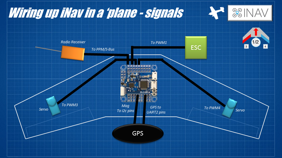
Connecting the Servos

The next thing to do is connect the servos and ESC to the flight controller. This part is easy (as long as the flight controller has the pin headers soldered onto the PWM outputs!). We are setting up a flying wing so we are going to follow the connection diagram on the top right-hand side of the image. Install the servo to the corresponding PWM output. Here it is left elevon (looking from the top) into PWM 3, right elevon into PWM 4.
Summary
So now that’s the connections made, not too bad, was it? You can put the soldering iron and crimp tool away for a while as in the next installment of this series we will be looking at setting up the model in the iNav software. cavenues.com.auKeep the prop off any motor you have installed in the model and also use an ohm-meter to check that there are no shorts between the positive and GND wires on the battery connections too. Visually inspect the installation at the end and make sure that no contacts have been accidentally bridged and nothing is touching something it shouldn’t be. Make sure you can mount the board in the model flat (or as flat as you can) and that you can get to the USB cable... In the next article, we will look at the process for calibrating and setting up the model. If can be helpful if it’s a model you’ve flown traditionally as you will know where all of the control surfaces need to be physically for straight and level flight. Until next time!
Written by Painless360
Hear it First: Join our Mailing List
Sign up to receive new product updates, exclusive discounts, news, and more!