The installation of servos and pushrod linkages in your model airplane, or anything else for that matter, is an extremely important, and vital part of the build, if this installation fails, the results can be terminal.
First, let's take a look at mounting the servo. All servos are supplied with a servo mounting kit which comprises screws, rubber grommets or rubber pads, metal ferrules, and some servo horns. Models of all sorts are subject to vibration, but more so airplanes and helicopters, especially if using I.C./Nitro engines. Constant vibration to a servo will eventually cause it to fail which is why the manufacturers supply each servo an anti-vibration mounting kit. It is important that the rubber grommets/pads are used, and also in the correct way (please see the pictures below for the correct way to install the metal ferrules).
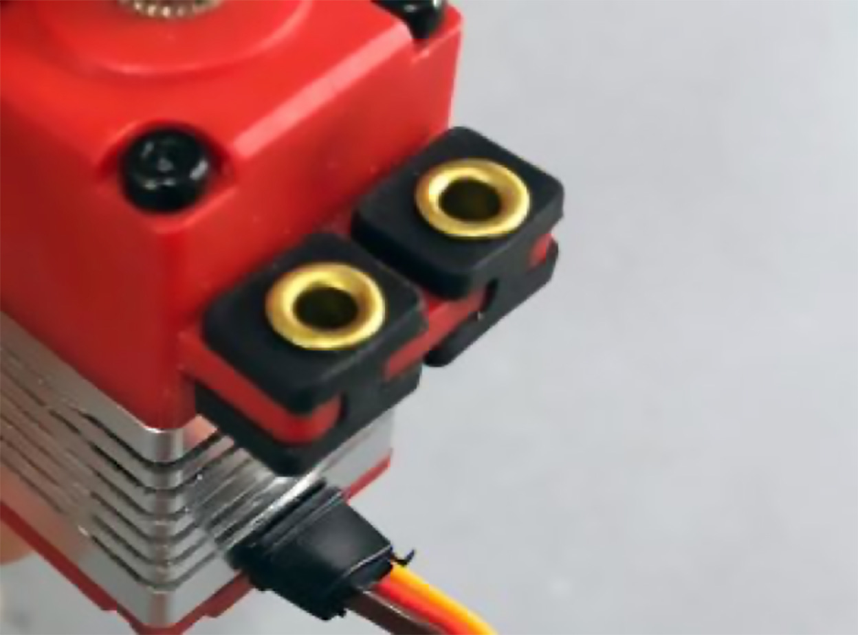
This picture shows the ferrules installed with the flange on the top, this is incorrect.
This picture shows the ferrules installed correctly with the flange on the underside of the mounting grommet.
Most servo screws that are supplied to mount servos have a molded washer, if not, then separate washers are usually supplied. These screws (with washers if separate) pass through the ferrules from the top and screw into your servo mount. Do not over-tighten, ensure they just touch the top of the ferrule and stop there, once the screws are in position, you should be able to move the servo slightly against the sponginess of the rubber grommets/pads. Also, ensure the servo is mounted so that it is not touching the sides of the fuselage or any part of the model, as this will also subject the servo to unwanted vibration.
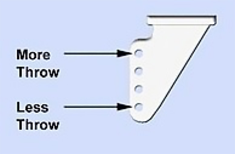
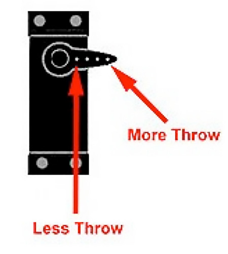
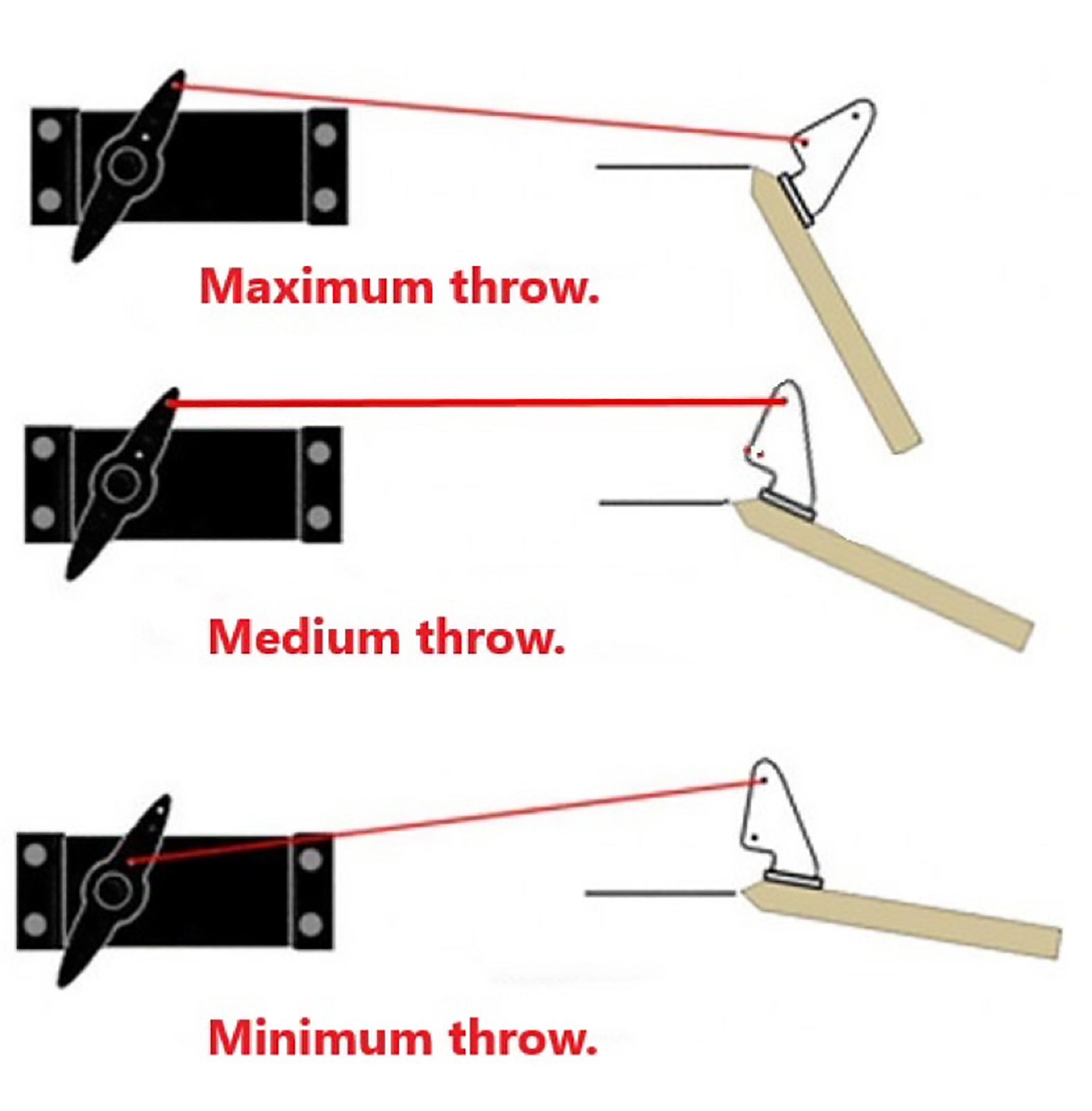
A good mechanical setup of servos is much better than installing them into your model, then relying on lots of sub-trim, end point adjustment, etc to achieve the required setup. A servo setup using endpoint adjustment close to 100% each way will provide better control surface resolution which will make for smoother flying. A servo with its end-point adjustment squeezed down to say 25% each way is not conducive to smooth flying and a good setup. Using lots of sub-trim is also not good, it is far better to have the sub-trim set at 0% and to then mechanically adjust the length of the pushrod to achieve a neutral control surface (sub-trim should only be used for fine tuning, not for correcting a badly setup control surface). Below is an example of how you can get your control surfaces operating somewhere close to the throws you require before you need to fine-tune with your end-point adjustments. As a general rule, it is also best to have your servo horn set at 90° to the pushrod where possible to stop any differential movement.
I will just touch on mounting the control horns to the control surfaces as this is also an important part of your servo, to control surface setup. This example is using the most popular T-style control horns which come with most kit, and ARTF models. As shown in the pictures below, the horn needs to be mounted in line with the pushrod, and the pushrod holes in the horn need to be in line with the hinge line of the control surface.
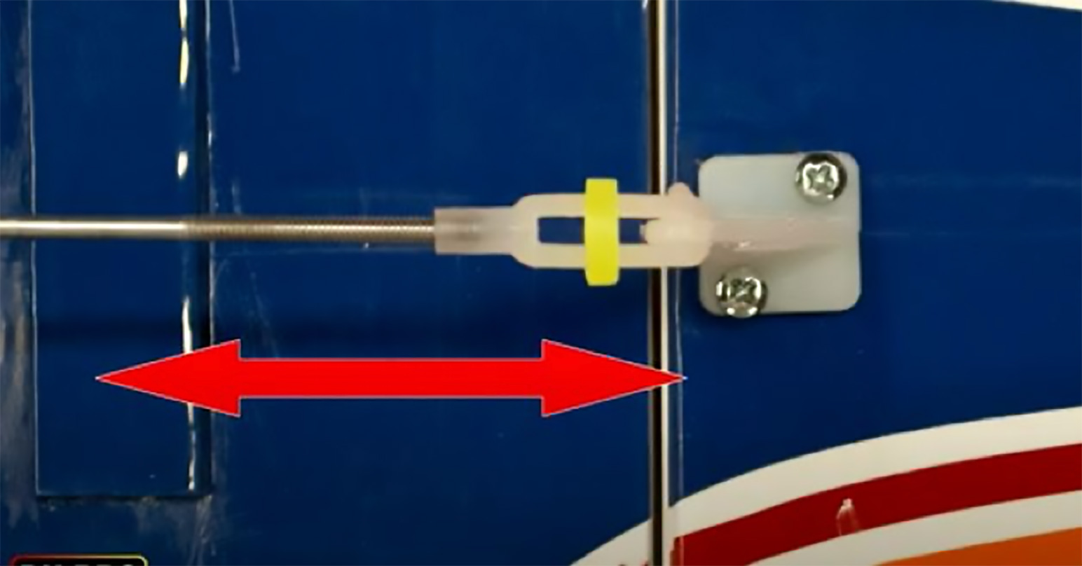
Make sure the horn is in line with the pushrod.
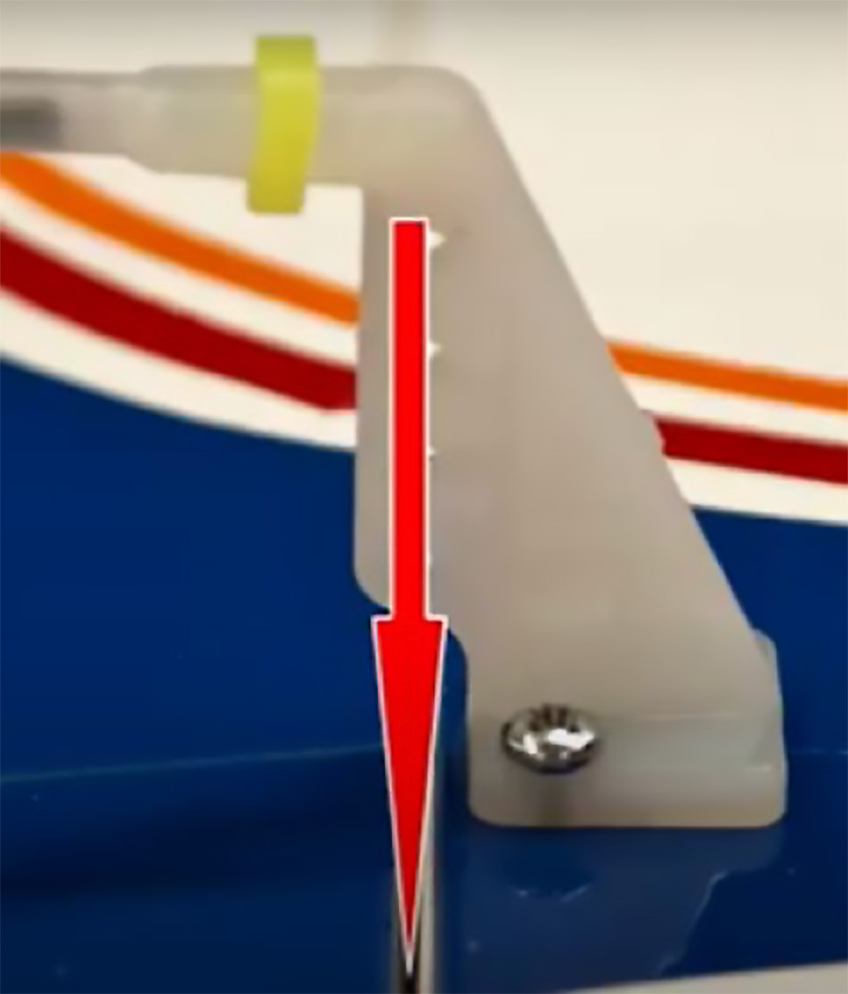
The pushrod holes must be inline with the hinge line.
To position and mount the horn in the correct place, it is always a good idea to use a small piece of clear double-sided tape (something like Scotch or 3M) attached to the base of the horn. You can then accurately position it on the control surface, and it will stay there whilst you drill the holes in the control surface for the mounting screws using a pin vice and a small drill.
So, please, always use the supplied servo mounting set to protect your servos from vibration, and take the time to set up your servos, pushrods, and control horns correctly to ensure a much smoother, better, and easier model to control.
See our full range of these in stock servos
---
Hear it First: Join our Mailing List
Sign up to receive new product updates, exclusive discounts, news, and more!