Introduction:
In the previous articles, we’ve covered what iNav is and what it can do for a fixed-wing pilot and we’ve also covered how to wire everything up. Adding iNavflight to your fixed-wing model can provide you will excellent stabilization and cheap, effective OSD setup but it can also provide GPS flight modes and allow you to even fly missions autonomously.
Using a $20 flight controller and a $20 GPS unit we can create a ‘smart’ model that will rival some of the systems costing 10 times as much.
In this article, we will continue to look at the technology but this time we'll cover the setup steps for your fixed-wing model. In this article, we will set up the iNav software, calibrate the flight controller and control surface movement, and get ready for the next steps...
All of this detail is covered in the iNavflight documentation. I’d always recommend having a look at it as the software and firmware I’m about to discuss is constantly being updated and improved so things may change a little from when this article was written (the version used at the time of writing is iNav V1.7).
So, let’s look at how we can set up the model in software...
So what next?
Let us quickly recap what we’ve achieved so far.
Step One: We’ve downloaded and installed iNav onto our computer.
Step Two: We’ve connected the servos, ESC, and radio receiver and attached the flight controller to the airframe (hopefully as flat as you can manage).
Now we can move onto the software setup on this thing...
One final thing before you start the computer up...
Most flight controllers will fly a poorly setup fixed-wing model but fly a good setup model better.
Personally, I’d recommend flying the model and making sure everything is working well, and trimming the control surfaces for straight and level flight. Most models need a little trim on the elevator and aileron and testing that the COG is spot on will help too.
Setup the radio as you would normally and fly it in calm weather. Make sure it flies true and use the trim tabs to get it to spot on so it flies straight and level at mid throttle. Once you’ve done that, land it and make a note of the position of all of those control surface positions as you’ll be setting them up to be in those exact positions again when you come to configure the software.
I normally take a few measurements and photos that can act as a reference before I move to the next step. If needed reset the linkages on the model so that the relationship between the servo arm and the control rod is as close to 90 degrees as possible and adjust mechanically for the control surface to be in the same position as you noted for the rudder, elevator, and aileron. This will mean that we can set up the position of the servo in the software to be exactly the neutral point and provide equal throws in each direction.
Remember that moving the COG will affect the trim of the aircraft so do this with the battery you intend to use with the flight controller.
This entire step here is optional. If you want to you can skip it but click out of the self-level modes in iNavflight will cause the model to change attitude, sometimes violently, so I’d strongly recommend that you do...
Now we know how the model likes to be flown, let’s turn on the computer!
Setting up the model on your radio.
One thing that can catch a new iNavflight (or any plane with a flight controller actually) is that you need to remove all of the mixing from your model set up on your radio.
If you followed my advice and flew the model without the flight controller then you maybe have a few mixes on your radio. You absolutely will if you’re flying a ‘V’ tail or wing type model.
You now need to re-set all the trims on the model and remove any mixing you have. Even with a wing, you should have each of the main controls set up to operate independently – elevator, aileron, rudder, throttle, and a mode switch should be set up and move on their own.
Also, consider adding another channel to act as the arming switch too. It’s handy for fixed wings with flight controllers...
Let’s now set up the receiver in iNav.
With the prop not installed for safety, power up the radio and connect the flight controller to the PC and start iNavflight. Connect to the flight controller again and check that the receiver LED is lit and showing that it has a connection with the radio. If it’s not powered then you may have to plug a flight battery into the motor ESC/BEC to power it.
Click into the receiver tab and move the controls to check a few things...
Direction
Move each of the controls one at a time and check the direction is ok. If any of the channels are not as below then reverse them on the radio...
- Throttle stick push away - increased value
- Yaw (Rudder) stick right - increased value
- Pitch (Elevator) stick push away - increased value
- Roll (Ailerons) stick right - increased value
Range of movement (Radio)
Test that each of the main controls moves between 1000 µs and 2000µs. Some radios like the Taranis and Q X7 like to push the channels beyond what is considered the normal range. I use the menus on the radio to reduce the range of the throttle, elevator, aileron, and rudder channels to be around 1060 - 1940µs (if you’re using OpenTX on your radio, use the ‘Servo’ menu to do this, I find about 97% of the travel in both directions is enough to sort this out).
I was helping a fellow pilot fix a model just yesterday and this was the problem causing arming issues.
Channel direction.
The next thing for us to check while we are in the Receiver tab of the GUI in iNavflight is to check that each of the controls is moving in the right direction too.
Throttle and elevator (pitch) controls, the value should increase and move to the right as the throttle stick moves towards the top of the radio.
As the rudder and aileron controls move to the right side of the radio, the values for those channels should increase too.
If this isn’t the case for any of these channels then use the channel reversing options in the radio to make sure they are moving in the correct direction.
Check that you can also see movement from at least two other switches/channels on the radio too. You’ll need one for selecting the flight mode (I use a three-position switch for that) and one for arming the model too.
Centre channel value.
The final thing to test is that each of the main controls also settles to 1500µs. To do this, use the sub-trim menu on your radio. On a Radio using OpenTX, while still in the servo menu of the radio change the sub-trim values for the aileron, elevator, and rudder channels so they come to rest at exactly 1500µs. Don’t worry if they flicker around that value slightly. That’s normal on most radios. Move the controls and let them settle back to the middle position to double-check.
Ok, now the radio is set up and moving as needed. I’d reset any fail-safes you may have on the receiver (usually this is done by re-binding the receiver) and then we can start to set up the movement of the servos and control surfaces on our model now.
Setting up the servos and throws
Remember how I mentioned that we noted the position of the control surfaces for straight and level flight at the start? This is where we will use that detail. It’s also handy to know what the throw or deflection of each of the control surfaces needs to be on your model too. See why doing this on a model you’ve already flown and trimmed is useful?
Analog servos, used in cheaper models usually work fine but for the best performance, digital servos are recommended.
For this bit, we will need to be in the Servos tab within iNavflight.
With the radio on and connected to the model (still without those props off – safety first!), move each of the controls one by one, and observe the movement. If the servo and control surface are reversed then change the polarity in the ‘Direction and Rate’ line for that servo. I.e. if it’s +100 then change it to -100 and vice versa.
Now we’ve got that sorted we need to center the servos so that the arm and control rod is at 90 degrees. This is so that there is an equal throw in each direction when we move the control surface.
Use the Servo Midpoint to move the center position for each of the servos so that this is the case. Don’t worry about the position of the actual control surface yet, we’ll take care of that in a moment.
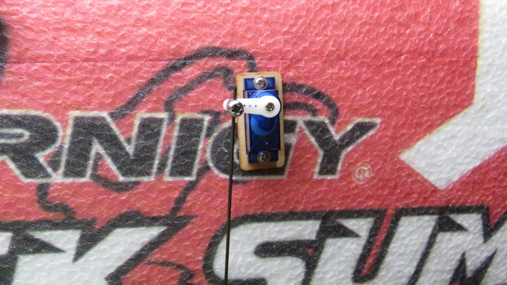
Now you’ve got all of the lineages at 90 degrees we can unhook the control rods from the servos and manually adjust the linkages so that with the servos at that 90-degree position the control surface is at the exact same position as when we trimmed the model for straight and level flight. This way iNavflight and the control electronics will default to the control positions needed for level flight and also give equal throws in both directions about that position.
The last thing here is to play with the amount of movement on each of the controls. Either use the position of the linkage to increase/reduce the throw of the Elevator, Aileron, and Rudder or simply adjust the value of movement in the Servos’ tab in iNav to set up the correct amount. I usually find that the default of +100 (or -100!) is too much and usually end up reducing it to something like 60-80 for enough travel on the model.
By this point, everything should be moving in the right direction as you move the sticks on the radio; the throw and neutral position should be as it was when you flew the model without the extra pieces installed. Do one final ‘high five’ test to make sure that everything is as expected.
But now you have a little clever co-pilot in there that can fly this model too!
Checking iNavflight is working well.
In the modes tab set up one of the flight modes to be angle (this is the simple self-level mode) and the other is set to arm the model.
Check which AUX channel is connected to which switch in the recover tab as you move them on the radio and then select the relevant AUX channel from the dropdown list in the ‘Modes’ tab in the GUI. Move the switch to the position you want that mode to be active in and then move the two sliders that enclose a blue segment to bracket the little slider that shows the value of that channel.
Save that and make sure that ANGLE mode is selected on the model (it will be colored on the left-hand side when selected).
Now the flight controller will attempt to keep the craft level when you return the controls to the center position. Also, try to counteract any external forces to make sure it stays level.
Place your hand on the wing and control surface and move the plane about the axis. You should feel the aileron push up against your hand as you raise the wing. There won't be a lot of movement, that’s normal, but you will feel it rise to automatically counter the un-commanded roll move.
Place your hand on the rear tail feathers and test the elevator and aileron in the same way. You should feel the control surface move in the same direction as the un-commanded movement.
If it does, then you’ve done all of the basic setups for the model.
Next time…
We’re almost there and ready to try a flight. In the next article, we will get to that part.
So please join me as we start to get towards the end of this series and look at the flight modes, final checks, and testing of your plane and cover some of the common hiccups you can have with a new setup.
See you then!
Written by Painless 360
Hear it First: Join our Mailing List
Sign up to receive new product updates, exclusive discounts, news, and more!


