
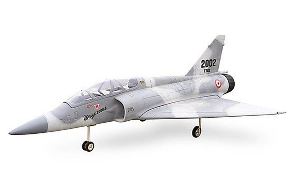
The flyfly 90mm mirage is known the world over as one of the all-time classics.
It is an exceptional flyer at both high and low speed and it can even be hand-launched via a bungee cord or if you’re really adventurous, straight up vertical out of your hand. If you’re prepared to put in a few hours’ work you’ll have a great jet that you’ll enjoy flying. There is no right or wrong way to build the 90mm Mirage. I can only show you what I’ve done and what worked for me. I know there are many who have spent countless hours adding a fiberglass skin to the aircraft. Painting the aircraft in a military scheme and applying decals to match, however, I’m a little lazy. I prefer to fly the mirage-like I stole it as I’ve never been one to muck around with fancy paint schemes and decals. I’d hate to put all those additional hours into a build and smash into the ground when I get just a little too low to the ground.
What is in the box
- Fuselage
- Wing Halves
- Rudder
- Canopy Halves
- Nose Cone
- Accessory Pack
- Plywood Parts
What will you need
- 6mm Square Carbon Tube
- 2 x Corona Digital Metal Gear Low Profile Servos
- 2 x 40cm extension Leads
- 90mm 12 blade high-Performance EDF
- 8mm Blade Adapter
- 1500kv Fan Drive Motor
- 100amp ESC
- 5amp BEC (6S capable)
- UHU Por Glue
- Polyurethane Glue (Gorilla Glue)
Get yourself a beer or perhaps a warm beverage depending where you are in the world. Clear a decent area on your workbench and place all the parts out on the table.
Joining Wing Halves
The first step is to reinforce the wing. You will need to add a carbon strip into each wing to provide structural integrity. The manual does not call for this, however, it is highly likely the wing will fail without it. There is no hard and fast way of getting this right. Bring the two wing halves together and lay the carbon on top of the wing so that you can gauge where the carbon will fit best. Using a 6mm drill bit drill into the wing from roughly the center of the wing halves. Once you have made an opening you can begin to dry-fit the carbon tube and assess if more material needs to be removed. The wing halves must join together neatly without needing to apply any pressure or force with the carbon in the wing. If you need to remove more foam from the wings this is fine as the wholes will be filled with expanding foam. Once you are happy with the dry fit you can begin to spray a fine mist of water on the surfaces where glue will be applied. Add a small amount of polyurethane glue underneath the carbon rod and into the wing halve so they will be permanently bonded. Remember that less is more when it comes to polyurethane glue as it will expand and you don’t want it escaping out the sides as it looks messy and cannot easily be cleaned up until it's cured. The instructions call for the servos to be facing the bottom of the model, however, if you intend to belly land this model it's better if they come through the top of the wing so that they are not damaged by a landing. Do use good quality highly accurate servos as the model will perform poorly if the servos don’t center correctly. You will need servo extension leads 40-50cm that will be run from the servos, through the wing, and into the fuse as per the instructions.
EDF FAN and Motor
I decided not to glue the fan into the model as per the manual – preferring to separate part of the fuselage so that it could be easily removed for maintenance or upgrades. The motor wires are kept in place by a loop of Velcro and a few patches of velcro placed on the fuse so that the wires can be removed as required. I went with a changesun 12 blade 90mm fan and a Fandrive 1500kv 3968 inrunner. This motor is fitted with an 8mm shaft so be sure to grab an 8mm adapter if you use these parts. Using this setup on a 6S pack you will get more than 1.1 thrusts. In fact, the model can pull away vertically with ease should you wish to launch it this way. I went with a 6s 120amp YEP ESC which is more than capable and it also includes BEC which is very handy.
Telemetry
 I used a FRSKY telemetry sensory so that I can monitor the battery usage. If you’re going to use this item I suggest you remember to install the sensor meter prior to fitting the XT90 connector. I highly recommend telemetry sensors in an EDF. The flight times are short so it makes sense to take readings in flight and get every last drop out of the battery without pushing it beyond 80% of capacity. I used 10 gauge wire between the ESC and the motor and although on the thin side you should remember that it's 3phase and only being used 2/3rd of the time. I used #10 gauge wire from the ESC to the motor.
Cockpit
The canopy was easy enough although care should be taken as the clear plastic is brittle. You will also need to cut the bottom half before both halves can be brought together. Do not use CA glues on plastic canopies as this will without a doubt lead to the frosting of the canopy. Although this won’t damage the canopy it looks unsightly. There are specific canopy glues however I’ve used UHU POR for a long time and it works a treat. It certainly did a great job on the Mirage and it also foam safe. You will need to remove some foam from the cockpit sides so that the canopy fits properly. Using some of the ply pieces included with the model you will need to glue a tongue onto the canopy so that it can be located into the front of the cockpit. The kit included a canopy hatch, however, I used a magnet.
Hinges
The model is fitted with fiber tape hinges, however, you should replace them as they are not suitable for a model of this size. The factory paints the model and then applies the tape which means the tape, although very strong is now only as strong as the bond between the paint and the foam. So, the best option here is to replace it out. A good set of hinges are the HobbyKing Nylon and pinned hinges.
Control Arms
For the highest resolution using a tall control horn arm such as an adjustable control horn 3x34mm (5sets). You must use one of the innermost servo control horn holes so that the control surface has the highest resolution possible. Given the control, the surface is so large-small movements have a dramatic effect on the flight characteristics of the aircraft. Jerky, low-resolution movements make for poor handling in this aircraft. It is for the very same reason that you buy good quality digital servos.
Fuselage
The wing is joined to the fuse via bind nuts and 4mm screws as per the manual and there is no modification needed to this arrangement. The vertical stabilizer is fixed to the fuse by contact adhesive. I used UHU POR which is more than adequate in this situation.
Center of Gravity
CG is as per the manual at 390mm from the trailing edge. This is fine.
Battery placement
To balance the model at 390mm from the trailing edge the battery will need to rest inside the model slightly. You will need to remove some foam from inside the cockpit to facilitate this. Once you have worked out where your battery will need to be positioned I glue a strip of 10mm ply to the fuse so that the battery can be pushed up against it and secured with velcro in the cockpit area.
| Control Surface Throws | |
|---|---|
| Aileron: | 45% |
| EXPO: | -30% (Futaba) |
| Elevator: | UP 50% |
| Elevator: | Down 40% |
| EXPO: | -30% |
| Steering: | 40% |
| EXPO: | 80% |
| Control Surfaces Travel | |
| UP: | 30mm |
| DN: | 20mm |
| Flight-Report | |
Be on the alert during the maiden as the aircraft will likely want to torque roll to the left. Get up to height and reduce throttle and begin to trim out the aircraft. If possible have someone with you that can adjust trims for you as you fly. Once trimmed out go up high and get a feel for stall speeds. The mirage is a wonderful aircraft that flies and lands beautifully. I’m sure you’ll thoroughly enjoy building and flying the mirage. Happy Landings. Written by Gozarian
Hear it First: Join our Mailing List
Sign up to receive new product updates, exclusive discounts, news, and more!